Ideal for liquid flow measurement on/off the oil field, this ½" (12.7 mm) flow meter can withstand the demands of the most rigorous flow measurement applications. In addition, it offers accurate and repeatable flow measurements from 0.75 to 7.5 gpm (25 to 250) and has a maximum pressure of 5000 psi and male BSPP end connections.
Ideal for liquid flow measurement on/off the oil field, this ½" (12.7 mm) flow meter can withstand the demands of the most rigorous flow measurement applications. In addition, it offers accurate and repeatable flow measurements from 0.75 to 7.5 gpm (25 to 250) and has a maximum pressure of 5000 psi and male BSPP end connections.
Whether on or off the oil field, this turbine flow meter maintains measurement accuracy and mechanical integrity in the corrosive and abrasive fluids commonly found in water flood projects and many industrial applications.
Features
Installation
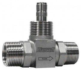
This turbine meter is simple to install and service. It operates in any orientation (horizontal to vertical) as long as the "flow direction" arrow is aligned in the same direction as the actual line flow. For optimum performance, the flow meter should be installed with a minimum of 10 diameters upstream straight pipe length and 5 diameters downstream straight pipe length.
Operating principle
Fluid entering the meter passes through the inlet flow straightener which reduces its turbulent flow pattern and improves the fluid's velocity profile. Fluid then passes through the turbine, causing it to rotate at a speed proportional to fluid velocity. As each turbine blade passes through the magnetic field at the base of the transducer, an AC voltage pulse is generated in the pickup coil. These pulses produce an output frequency proportional to the volumetric flow through the meter.
K-factor
The K-factor represents the number of output pulses transmitted per gallon of fluid passing through this turbine meter. Each turbine has a unique K-factor. However, turbine meters are not functionally consistent throughout the full flow range of the meter. There are several forms of friction inherent in this turbine meter that retards the rotational movement of the turbine rotor. These frictional forces include: magnetic drag, created by electromagnetic forces of pickup transducers; mechanical drag, due to bearing friction; and viscous drag, produced by flowing fluid. As flow increases, the frictional forces are minimized and the free-wheeling motion of the turbine rotor becomes more linear (proportional to flow). The K-factor becomes relatively constant and the linear throughout the balance of the linear flow range. This is approximately a 10:1 turndown ratio from the maximum flow rate down to the minimum flow rate.
Applications
| Flow Ranges | 0.75 to 7.5 gpm (2.8 to 28.4 lpm) 25 to 250 bpd 4.1 to 41 m3/d |
| Maximum Pressure | 5000 psi |
| Approximate K-Factor Pulse/Gal | 13,000 |
| Accuracy | ±1% of reading over the upper 70% of the measuring range |
| Repeatability | ±0.1% |
| Turndown Ratio | 10:1 |
| Calibration | Water (NIST traceable calibration) |
| Strainer Mesh | 60 |
| End Connections | 1" male BSPP |
| Operating Temperature | -150 to 350°F (-101 to 177°C) |
| Materials | Body: 316 stainless steel Rotor: CD4MCU stainless steel Rotor shaft: Tungsten carbide Rotor support: 316 stainless steel |
| Magnetic Pickup | Body thread: ⅝-18 UNF Termination type: 2-pin MS Mounthing thread electrical: MS3106-10SL-4S Output: MAG (mV Freq) Resistance: 1500 Ω ±10% Gauss: ~1200 Temperature range: -150 to 330°F (-101 to 165°C) Pinouts: A = Coil, B = Coil (no polarity) |
| Dimensions | Meter: ½" (12.7 mm) Bore size: 1" (25.4 mm) End-to-end length: 4" (101.6 mm) |