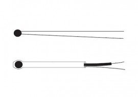
Image is for reference only, refer to product info for complete details.
Precision matched to a standardized resistance curve, this epoxy-coated NTC thermistor element offers a 30,000 Ω resistance at 25°C with ±0.1°C interchangeability. It operates over 32 to 158°F (0 to 70°C). It suits OEM and laboratory temperature sensing.
Precision matched to a standardized resistance curve, this epoxy-coated NTC thermistor element offers a 30,000 Ω resistance at 25°C with ±0.1°C interchangeability. It operates over 32 to 158°F (0 to 70°C). It suits OEM and laboratory temperature sensing.
OMEGA's 44000 Series thermistor elements are epoxy-coated thermistor beads precision matched to five standardized resistance curves. They are available in interchangeabilities of ±0.1 or ±0.2°C.
The Steinhart-Hart Equation has become the generally accepted method for specifying the resistance vs. temperature characteristics for thermistors.
Accuracy tolerances for thermistor sensors are expressed as a percentage of temperature. This is also referred to as interchangeability. We list two basic accuracy/interchangeability specifications for our thermistors, ±0.10°C and ±0.20°C from 32 to 158°F (0 to 70°C).
While thermistors are generally very accurate and stable devices, conditions such as over-temperature exposure, humidity, mechanical damage or corrosion can cause uncontrolled changes in the resistance vs. temperature characteristics of the device. Once this characteristic has been altered, it cannot be re-established.
This is one reason why most thermistors with a ±0.1°C interchangeability specification are rated for use at temperatures somewhat lower than those with an interchangeability of ±0.2°C.
The suggested operating current for bead-style thermistors is approximately 10 to 15 µA. Thermistors can experience self-heating effects if their operating currents are high enough to create more heat than can be dissipated from the thermistor under operating conditions. If higher operating currents are used, it is suggested that a self heating test be performed to insure the accuracy of the measurement.
The dissipation constant is the power in milliwatts that will raise the resistance of a thermistor by 1.8°F (1°C) over its surrounding temperature. Typical values include 8 mW/°C in a stirred oil bath, or 1 mW/°C in still air.
The time constant is the time required for a thermistor to react to a step change in temperature. For example, if exposed to a change from 32 to 212°F (0 to 100°C), the 63% time constant would be the time required for the thermistor to indicate a resistance at 145°F (63°C).
Typically, bare thermistors suspended by their leads in a well stirred oil bath will have a 63% response time of 1 second maximum. PFA encased thermistors exposed to changes in air temperature will typically have a 63% response time of 2.5 seconds maximum.
Features
Applications
| Series | 44032 |
| Maximum working temperature | 75°C (165°F) or 150°C (300°F) |
| Type | thermistor element |
| Interchangeability | ±0.1 or ±0.2°C from 0 to 70°C (32 to 158°F) |
| Type | NTC thermistor bead element |
| Suggested operating current | 10 to 15 µA |
| Resistance at 25°C | 30,000 Ω |
| Dissipation constant | 8 mW/°C in a stirred oil bath, or 1 mW/°C in still air |
| Interchangeability | ±0.1°C from 0 to 70°C |
| Time constant, bare thermistor in stirred oil bath | 1 second maximum (63% response) |
| Maximum working temperature | 167°F (75°C) |
| Time constant, PFA encased in air | 2.5 seconds maximum (63% response) |
| Construction | Epoxy-coated thermistor bead |
| Resistance @ 25°C | 30,000 Ω |
| Storage and working temp for best stability | -112 to 167°F (-80 to 75°C) |
| Storage and maximum working temperature | 75°C (165°F) |
| Resistance curves | Precision matched to 5 standardized resistance curves |
| Interchangeability @ 0 to 70°C | ±0.1°C |
| Resistance vs. temperature characteristic | Steinhart-Hart equation: 1/T = A + B[Ln(R)] + C[Ln(R)]3 |
| Temperature for best stability | -80 to 75°C (-110 to 165°F) |
| Steinhart-Hart constants (R25 = 30000 Ω) | A = 9.376 x 10⁻⁴, B = 2.208 x 10⁻⁴, C = 1.276 x 10⁻⁷ |
| Dimensions | 2.4 mm (0.095") diameter bead with #32 tinned copper wire Bead with PFA sleeving: 2.8 mm (0.11") diameter bead, PFA tubing, 32 AWG silver plated copper or alloy 180 (copper/nickel), 50.0 mm (2") minimum, 76.2 mm (3") |
| Suggested operating current | Approximately 10 to 15 μA |
| Dissipation constant | Typical values include 8 mW/°C in a stirred oil bath, or 1 mW/°C in still air |
| Time constant | 63% response time of 1 second maximum for bare thermistors suspended by their leads in a well stirred oil bath; 2.5 seconds maximum for PFA encased thermistors exposed to changes in air temperature |
| Bead construction | Epoxy coated thermistor bead |
| Bead diameter | 0.095" (2.4 mm) diameter bead |
| Lead wire | 32 AWG silver plated copper or alloy 180 (copper/nickel) |
| Optional PFA sleeving | 0.11" (2.8 mm) diameter bead with PFA sleeving; available with PFA sleeving over 1 lead wire and PFA overall (change middle digit of model number to "1" (2.5 cm)) |
| Series | 44032 |
| Maximum working temperature | 75°C (165°F) or 150°C (300°F) |
| Type | thermistor element |
| Interchangeability | ±0.1 or ±0.2°C from 0 to 70°C (32 to 158°F) |
| Type | NTC thermistor bead element |
| Suggested operating current | 10 to 15 µA |
| Resistance at 25°C | 30,000 Ω |
| Dissipation constant | 8 mW/°C in a stirred oil bath, or 1 mW/°C in still air |
| Interchangeability | ±0.1°C from 0 to 70°C |
| Time constant, bare thermistor in stirred oil bath | 1 second maximum (63% response) |
| Maximum working temperature | 167°F (75°C) |
| Time constant, PFA encased in air | 2.5 seconds maximum (63% response) |
| Construction | Epoxy-coated thermistor bead |
| Resistance @ 25°C | 30,000 Ω |
| Storage and working temp for best stability | -112 to 167°F (-80 to 75°C) |
| Storage and maximum working temperature | 75°C (165°F) |
| Resistance curves | Precision matched to 5 standardized resistance curves |
| Interchangeability @ 0 to 70°C | ±0.1°C |
| Resistance vs. temperature characteristic | Steinhart-Hart equation: 1/T = A + B[Ln(R)] + C[Ln(R)]3 |
| Temperature for best stability | -80 to 75°C (-110 to 165°F) |
| Steinhart-Hart constants (R25 = 30000 Ω) | A = 9.376 x 10⁻⁴, B = 2.208 x 10⁻⁴, C = 1.276 x 10⁻⁷ |
| Dimensions | 2.4 mm (0.095") diameter bead with #32 tinned copper wire Bead with PFA sleeving: 2.8 mm (0.11") diameter bead, PFA tubing, 32 AWG silver plated copper or alloy 180 (copper/nickel), 50.0 mm (2") minimum, 76.2 mm (3") |
| Suggested operating current | Approximately 10 to 15 μA |
| Dissipation constant | Typical values include 8 mW/°C in a stirred oil bath, or 1 mW/°C in still air |
| Time constant | 63% response time of 1 second maximum for bare thermistors suspended by their leads in a well stirred oil bath; 2.5 seconds maximum for PFA encased thermistors exposed to changes in air temperature |
| Bead construction | Epoxy coated thermistor bead |
| Bead diameter | 0.095" (2.4 mm) diameter bead |
| Lead wire | 32 AWG silver plated copper or alloy 180 (copper/nickel) |
| Optional PFA sleeving | 0.11" (2.8 mm) diameter bead with PFA sleeving; available with PFA sleeving over 1 lead wire and PFA overall (change middle digit of model number to "1" (2.5 cm)) |