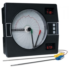
Built for process temperature recording and control, this circular chart recorder is supplied with Programmable Universal Input, 1-CH, TC. It has thermocouple input range, j of 32 to 1400°F (0 to 760°C). It also suits environmental chamber data logging.
Built for process temperature recording and control, this circular chart recorder is supplied with Programmable Universal Input, 1-CH, TC. It has thermocouple input range, j of 32 to 1400°F (0 to 760°C). It also suits environmental chamber data logging.
The CT7000 microprocessor-based circular chart recorder measures, displays, records, and controls up to 2 process variables from a variety of inputs. Record and control functions, alarm settings, and other parameters are easily configured via the 3 front keys. The CT7000 offers a 10" (254 mm) circular chart and 4-digit LED display(s).
Features
Applications
| Series | CT7000 Series |
| Type | circular chart recorder |
| Input | Programmable Universal Input |
| Channels | 1-CH |
| Configuration | TC |
| Input | RTD |
| Configuration | mA |
| Configuration | V Measurement |
| Configuration | 0.1 hours to 999.9 hours Chart Time |
| Thermocouple Input Range, J | 32 to 1400°F (0 to 760°C) |
| Thermocouple Input Range, K | 32 to 2480°F (0 to 1360°C) |
| Thermocouple Input Range, T | -364 to 752°F (-220 to 400°C) |
| Thermocouple Input Range, E | 32 to 1382°F (0 to 750°C) |
| Thermocouple Input Range, N | 32 to 2372°F (0 to 1300°C) |
| Thermocouple Input Range, R | 392 to 3002°F (200 to 1650°C) |
| Thermocouple Input Range, S | 392 to 3002°F (200 to 1650°C) |
| Thermocouple Input Range, B | 392 to 3272°F (200 to 1800°C) |
| Thermocouple Input Range, C | 392 to 4172°F (200 to 2300°C) |
| RTD Input Range | 100 Ω (0.00385 Ω/Ω/°C), -220 to 752°F (-140 to 400°C) |
| Volts DC Input Range | 0 to 25 mV, 0 to 50 mV, 10 to 50 mV, 0 to 5 V, 1 to 5 V |
| Milliamps Input Range | 4 to 20 mA DC (via appropriate external shunt resistor) |
| Measurement Error Limit, Thermocouple Types J, K, T, E, N and RTD | ±0.25% of reading + 1° @ 77°F (25°C) |
| Measurement Error Limit, Type R, S, B, C Thermocouples | ±0.25% of span @ 77°F (25°C) |
| Measurement Error Limit, mV DC and V DC | ±0.25% of scaled span plus 1 least-significant digit |
| Ambient Temperature Error Limit | 0.01% of span per °C (1.8°F) deviation from 77°F (25°C) |
| Record Chart | 10" (254 mm) circular chart |
| Chart Range | -9999 to 9999 |
| Chart Rotation | User configurable from 0.1 to 999.9 hours per revolution |
| Digital Displays | 2 possible: 1 per installed pen; (4) 7-segment digits, 0.56" (14 mm) high, red LEDs |
| Line Voltage | 115/230 V AC ±10%, 50/60 Hz |
| Power Consumption | 25 VA maximum |
| Operating Temperature | 32 to 131°F (0 to 55°C) |
| Storage Temperature | -40 to 149°F (-40 to 65°C) |
| Humidity | 0 to 90% RH, non-condensing |
| Panel Cutout | 12.6 x 13.5" (321 x 343 mm) |
| Enclosure | Gasketed cover; black, structural foam |
| Windows | Plexiglass standard |
| Memory Backup | Battery, 5-year minimum life |
| Measurement Error Limit, mVdc and V DC | ±0.25% of scaled span plus 1 least-significant digit |
| Process Value Output Error Limit | ±0.5% of span |
| Record Error Limit | ±0.5% of chart span or better, typically; ±1.0% of chart span maximum |
| Display/Record Filter | 1 to 20 scans averaging |
| Process Filter | 1 to 20 scans averaging |
| Pen Response (Full Scale Deflection) | 20 s |
| Display Resolution | T/C and RTD: 0.1 or 1°; mVdc and V DC: 0.001, 0.01, 0.1 or 1 |
| Calibration Drift | Self-compensating for ambient temperature; all calibration values are stored in memory |
| Sensor Fault Detection | Displays "Hi" or "Lo" process input (10% above or below range) and sensor break "SnSr"; pen action on error condition is user configurable to 0 or 100% of chart span; on/off outputs go "off"; proportional outputs go to user-defined value from 0 to 100% |
| Pen Resolution | 0.15% of chart span |
| Recording Deadband | 0.3% of chart span |
| Chart Drive | DC stepper motor |
| Pen Type | Disposable fiber-tip |
| Pen Color | Pen 1, red; pen 2, green |
| Alarm Display | 2 alarm indications possible per pen; ALRM1 and ALRM2; red LEDs; single ALRM indication provided for controller pens |
| Status Display | LED indicates Out 1, Out 2, Man, Ramp, Soak, Seg 1 through Seg 6, process units as applicable |
| Alarms | Process, deviation (with hysteresis), deviation band |
| Relay Output (Optional) | SPST, 115 V AC: 250 VA, 230 V AC: 250 VA |
| SSR Driver Output (Optional) | Open-collector output, short circuit protected @ 100 mA maximum, provided 4 V DC at 20 mA or 3 V DC @ 40 mA |
| Current Output (Optional) | 0 to 20 or 4 to 20 mA DC into 650 Ω maximum (control or process value) |
| Proportional Band Output | 1 to 3000 units |
| Manual Reset (Integral) | -1500 to 1500 units |
| Auto Reset (Integral) | 0 to 100 repeats/minimum |
| Rate (Derivative) | 0 to 10 minimum |
| Cycle Time Output | 1 to 240 s |
| Transmitter Power Supply | Provides up to 40 mA at 24 V DC |
| Vibration | 0.5 to 100 Hz @ 0.2 g |
| ESD | No effect from 5000 V static charge over surface area |
| Common-Mode Rejection | 90 dB minimum; 24 V AC maximum for RTD input; 15 V AC maximum for other inputs |
| Normal-Mode Rejection | 85 dB minimum @ 60 Hz or greater |
| Keypad | Located on front cover, tactile feedback membrane keys |
| Dimensions | 13.2 x 15.1 x 3.6" (335 x 384 x 92 mm) |
| Weight | 20 lb (9.1 kg), maximum |
| Series | CT7000 Series |
| Type | circular chart recorder |
| Input | Programmable Universal Input |
| Channels | 1-CH |
| Configuration | TC |
| Input | RTD |
| Configuration | mA |
| Configuration | V Measurement |
| Configuration | 0.1 hours to 999.9 hours Chart Time |
| Thermocouple Input Range, J | 32 to 1400°F (0 to 760°C) |
| Thermocouple Input Range, K | 32 to 2480°F (0 to 1360°C) |
| Thermocouple Input Range, T | -364 to 752°F (-220 to 400°C) |
| Thermocouple Input Range, E | 32 to 1382°F (0 to 750°C) |
| Thermocouple Input Range, N | 32 to 2372°F (0 to 1300°C) |
| Thermocouple Input Range, R | 392 to 3002°F (200 to 1650°C) |
| Thermocouple Input Range, S | 392 to 3002°F (200 to 1650°C) |
| Thermocouple Input Range, B | 392 to 3272°F (200 to 1800°C) |
| Thermocouple Input Range, C | 392 to 4172°F (200 to 2300°C) |
| RTD Input Range | 100 Ω (0.00385 Ω/Ω/°C), -220 to 752°F (-140 to 400°C) |
| Volts DC Input Range | 0 to 25 mV, 0 to 50 mV, 10 to 50 mV, 0 to 5 V, 1 to 5 V |
| Milliamps Input Range | 4 to 20 mA DC (via appropriate external shunt resistor) |
| Measurement Error Limit, Thermocouple Types J, K, T, E, N and RTD | ±0.25% of reading + 1° @ 77°F (25°C) |
| Measurement Error Limit, Type R, S, B, C Thermocouples | ±0.25% of span @ 77°F (25°C) |
| Measurement Error Limit, mV DC and V DC | ±0.25% of scaled span plus 1 least-significant digit |
| Ambient Temperature Error Limit | 0.01% of span per °C (1.8°F) deviation from 77°F (25°C) |
| Record Chart | 10" (254 mm) circular chart |
| Chart Range | -9999 to 9999 |
| Chart Rotation | User configurable from 0.1 to 999.9 hours per revolution |
| Digital Displays | 2 possible: 1 per installed pen; (4) 7-segment digits, 0.56" (14 mm) high, red LEDs |
| Line Voltage | 115/230 V AC ±10%, 50/60 Hz |
| Power Consumption | 25 VA maximum |
| Operating Temperature | 32 to 131°F (0 to 55°C) |
| Storage Temperature | -40 to 149°F (-40 to 65°C) |
| Humidity | 0 to 90% RH, non-condensing |
| Panel Cutout | 12.6 x 13.5" (321 x 343 mm) |
| Enclosure | Gasketed cover; black, structural foam |
| Windows | Plexiglass standard |
| Memory Backup | Battery, 5-year minimum life |
| Measurement Error Limit, mVdc and V DC | ±0.25% of scaled span plus 1 least-significant digit |
| Process Value Output Error Limit | ±0.5% of span |
| Record Error Limit | ±0.5% of chart span or better, typically; ±1.0% of chart span maximum |
| Display/Record Filter | 1 to 20 scans averaging |
| Process Filter | 1 to 20 scans averaging |
| Pen Response (Full Scale Deflection) | 20 s |
| Display Resolution | T/C and RTD: 0.1 or 1°; mVdc and V DC: 0.001, 0.01, 0.1 or 1 |
| Calibration Drift | Self-compensating for ambient temperature; all calibration values are stored in memory |
| Sensor Fault Detection | Displays "Hi" or "Lo" process input (10% above or below range) and sensor break "SnSr"; pen action on error condition is user configurable to 0 or 100% of chart span; on/off outputs go "off"; proportional outputs go to user-defined value from 0 to 100% |
| Pen Resolution | 0.15% of chart span |
| Recording Deadband | 0.3% of chart span |
| Chart Drive | DC stepper motor |
| Pen Type | Disposable fiber-tip |
| Pen Color | Pen 1, red; pen 2, green |
| Alarm Display | 2 alarm indications possible per pen; ALRM1 and ALRM2; red LEDs; single ALRM indication provided for controller pens |
| Status Display | LED indicates Out 1, Out 2, Man, Ramp, Soak, Seg 1 through Seg 6, process units as applicable |
| Alarms | Process, deviation (with hysteresis), deviation band |
| Relay Output (Optional) | SPST, 115 V AC: 250 VA, 230 V AC: 250 VA |
| SSR Driver Output (Optional) | Open-collector output, short circuit protected @ 100 mA maximum, provided 4 V DC at 20 mA or 3 V DC @ 40 mA |
| Current Output (Optional) | 0 to 20 or 4 to 20 mA DC into 650 Ω maximum (control or process value) |
| Proportional Band Output | 1 to 3000 units |
| Manual Reset (Integral) | -1500 to 1500 units |
| Auto Reset (Integral) | 0 to 100 repeats/minimum |
| Rate (Derivative) | 0 to 10 minimum |
| Cycle Time Output | 1 to 240 s |
| Transmitter Power Supply | Provides up to 40 mA at 24 V DC |
| Vibration | 0.5 to 100 Hz @ 0.2 g |
| ESD | No effect from 5000 V static charge over surface area |
| Common-Mode Rejection | 90 dB minimum; 24 V AC maximum for RTD input; 15 V AC maximum for other inputs |
| Normal-Mode Rejection | 85 dB minimum @ 60 Hz or greater |
| Keypad | Located on front cover, tactile feedback membrane keys |
| Dimensions | 13.2 x 15.1 x 3.6" (335 x 384 x 92 mm) |
| Weight | 20 lb (9.1 kg), maximum |