Configured for TC/RTD/Resistance/Pot/mA/V I/P Type, Universal, mA/V O/P Type, this DIN rail transmitter suits linearised, electronic temperature measurement with rtd or tc sensor and power supply and signal isolator for 2-wire transmitters.
Configured for TC/RTD/Resistance/Pot/mA/V I/P Type, Universal, mA/V O/P Type, this DIN rail transmitter suits linearised, electronic temperature measurement with rtd or tc sensor and power supply and signal isolator for 2-wire transmitters.
Universal transmitter with input for RTD, TC, Ohm, potentiometer, mA and V, and output for current, voltage and 2 relays. Provides linearised electronic temperature measurement and 2 pairs of potential-free relay contacts, and is designed according to strict safety requirements making it suitable for application in SIL 2 installations.
Features
Applications
| Series | DRST-UR Series |
| Type | DIN rail transmitter |
| Input | TC/RTD/Resistance/Pot/mA/V I/P Type |
| Configuration | Universal |
| Output type | mA/V O/P Type |
| Output type | 2 Relays |
| Configuration | Process |
| Output type | Relay |
| Configuration | AC/DC |
| Configuration | 2300 V |
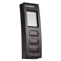
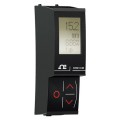
| Configuration | Programmer Display |
| Configuration | Display Programmer |
| Supply voltage, universal | 21.6...253 V AC, 50...60 Hz or 19.2...300 V DC |
| Maximum consumption | ≤ 2.5 W |
| Fuse | 400 mA SB / 250 V AC |
| Isolation voltage, test / operation | 2.3 kV AC / 250 V AC |
| Communications interface | Communication enabler DRST-CM / Programming front DRSL-DISPLAY |
| Signal / noise ratio | Minimum 60 dB (0...100 kHz) |
| Current output signal range | 0...20 mA |
| Voltage output signal range | 0...10 V DC |
| Relay functions | Setpoint, Window, Sensor error, Latch, Power and Off |
| Relay maximum voltage | 250 V RMS |
| Relay maximum current | 2 A / AC or 1 A / DC |
| Relay maximum AC power | 500 VA |
| Response time, temperature input (0...90%, 100...10%) | ≤ 1 s |
| Response time, mA / V input (0...90%, 100...10%) | ≤ 400 ms |
| Absolute accuracy (all input types) | ≤ ±0.1% of span |
| Temperature coefficient (all input types) | ≤ ±0.01% of span / °C |
| EMC immunity influence | < ±0.5% of span |
| Maximum wire size | 1 x 2.5 mm2 stranded wire |
| Screw terminal torque | 4.43 in-lb (0.5 Nm) |
| Protection degree | IP20 |
| Specifications range | -4 to 140°F (-20 to 60°C) |
| Calibration temperature | 68 to 82°F (20 to 28°C) |
| Relative humidity | < 95% RH (non-condensing) |
| Max. consumption | ≤ 2.5 W |
| Basic accuracy, mA | ≤ ±4 μA |
| Basic accuracy, Volt | ≤ ±20 μV |
| Basic accuracy, Pt100 | ≤ ±0.2°C |
| Basic accuracy, linear resistance | ≤ ±0.1 Ω |
| Basic accuracy, potentiometer | ≤ ±0.1 Ω |
| Basic accuracy, TC type E, J, K, L, N, T, U | ≤ ±1°C |
| Basic accuracy, TC type R, S, W3, W5, LR | ≤ ±2°C |
| Basic accuracy, TC type B (85...200°C) | ≤ ±4°C |
| Basic accuracy, TC type B (200...1820°C) | ≤ ±2°C |
| Extended EMC immunity, NAMUR NE 21, A criterion, burst | < ±1% of span |
| 2-wire supply (terminal 44...43) | 25...16 VDC / 0...20 mA |
| Input for RTD types | Pt10, Pt20, Pt50, Pt100, Pt200, Pt250, Pt300, Pt400, Pt500, Pt1000, Ni50, Ni100, Ni120, Ni1000, Cu10, Cu20, Cu50, Cu100 |
| RTD range, Pt10...Pt1000 | -328 to 1562°F (-328 to 1562°F (-200 to 850°C)) (IEC 60751) |
| RTD range, Ni50...Ni1000 | -76 to 482°F (-76 to 482°F (-60 to 250°C)) (DIN 43760) |
| RTD range, Cu10...Cu100 | -328 to 500°F (-328 to 500°F (-200 to 260°C)) (α = 0,00427) |
| Linear resistance range | 0 Ω to 10000 Ω |
| Potentiometer range | 10 Ω to 100 kΩ |
| Cable resistance per wire (maximum.), RTD | 50 Ω |
| Sensor current, RTD | Nom. 0.2 mA |
| Effect of sensor cable resistance (3-/4-wire), RTD | < 0.002 Ω / Ω |
| Short circuit detection, RTD | < 15 Ω |
| TC range, B | 32 to 3308°F (32 to 3308°F (0 to 1820°C)) (IEC 60584-1) |
| TC range, E | -148 to 1832°F (-148 to 1832°F (-100 to 1000°C)) (IEC 60584-1) |
| TC range, J | -148 to 2192°F (-148 to 2192°F (-100 to 1200°C)) (IEC 60584-1) |
| TC range, K | -292 to 2502°F (-292 to 2502°F (-180 to 1372°C)) (IEC 60584-1) |
| TC range, L | -328 to 1652°F (-328 to 1652°F (-200 to 900°C)) (DIN 43710) |
| TC range, N | -292 to 2372°F (-292 to 2372°F (-180 to 1300°C)) (IEC 60584-1) |
| TC range, R | -58 to 3200°F (-58 to 3200°F (-50 to 1760°C)) (IEC 60584-1) |
| TC range, S | -58 to 3200°F (-58 to 3200°F (-50 to 1760°C)) (IEC 60584-1) |
| TC range, T | -328 to 752°F (-328 to 752°F (-200 to 400°C)) (IEC 60584-1) |
| TC range, U | -328 to 1112°F (-328 to 1112°F (-200 to 600°C)) (DIN 43710) |
| TC range, W3 | 32 to 4172°F (32 to 4172°F (0 to 2300°C)) (ASTM E988-90) |
| TC range, W5 | 32 to 4172°F (32 to 4172°F (0 to 2300°C)) (ASTM E988-90) |
| TC range, LR | -328 to 1472°F (-328 to 1472°F (-200 to 800°C)) (GOST 3044-84) |
| Cold junction compensation (CJC) via external sensor 5910 | 20...28°C ≤ ±1°C; -20...20°C / 28...70°C ≤ ±2°C |
| CJC via internal CJC sensor | ±(2.0°C + 0.4°C * Δt) |
| Sensor error current, when detecting | Nom. 2 μA |
| Current input measurement range | 0...20 mA |
| Current input, programmable measurement ranges | 0...20 and 4...20 mA |
| Current input resistance | Nom. 20 Ω + PTC 50 Ω |
| Voltage input measurement range | 0...12 VDC |
| Voltage input, programmable measurement ranges | 0...1 / 0.2...1 / 0...5 / 1...5 / 0...10 and 2...10 VDC |
| Voltage input resistance | Nom. 10 MΩ |
| Current output, programmable signal ranges | 0...20 / 4...20 / 20...0 and 20...4 mA |
| Current output, load (maximum.) | 20 mA / 800 Ω / 16 VDC |
| Current output, load stability | ≤ 0.01% of span / 100 Ω |
| Current output, NAMUR NE 43 Upscale / Downscale | 23 mA / 3.5 mA |
| Current output limitation on 4...20 and 20...4 mA signals | 3.8...20.5 mA |
| Current output limitation on 0...20 and 20...0 mA signals | 0...20.5 mA |
| Current output, current limit | ≤ 28 mA |
| Voltage output, programmable signal ranges | 0...1 / 0.2...1 / 0...10 / 0...5 / 1...5 / 2...10 / 1...0 / 1...0.2 / 5...0 / 5...1 / 10...0 and 10...2 V |
| Voltage output, load (minimum.) | 500 kΩ |
| Relay hysteresis | 0...100% |
| Relay on and off delay | 0...3600 s |
| Relay sensor error detection | Break / Make / Hold |
| Relay maximum. voltage | 250 VRMS |
| Relay maximum. current | 2 A / AC or 1 A / DC |
| Relay maximum. AC power | 500 VA |
| Max. wire size | 1 x 2.5 mm2 stranded wire |
| Vibration | IEC 60068-2-6 : 2007; 2...13.2 Hz ±0.04" (1 mm); 13.2...100 Hz ±0.7 g |
| Installation | Installation Category II, Pollution Degree 1, Insulation Class II |
| Galvanic isolation | 4-port 2.3 kVAC |
| Safety | Designed as SIL 2 device |
| Ex / I.S. approval, FM | Class I, Div. 2, Group A, B, C, D; Class I, Div. 2, Group IIC; Zone 2; Max. ambient temperature for T5 140°F (60°C) |
| Marine approval | Det Norske Veritas, Ships & Offshore Standard for Certification No. 2.4 |
| Observed authority requirements, EMC | 2004/108/EC, EN 61326-1 |
| Observed authority requirements, LVD | 2006/95/EC, EN 61010-1 |
| Observed authority requirements, FM | 3600, 3611, 3810 and ISA 82.02.01 |
| Observed authority requirements, UL | Standard for Safety UL 508 |
| Observed authority requirements, EAC | TR-CU 020/2011, EN 61326-1 |
| Dimensions (H x W x D) | 4.29 x 0.93 x 4.09" (109 x 23.5 x 104 mm) |
| Dimensions, with DRSL-DISPLAY/DRST-CM (HxBxD) | 109 x 23.5 x 116/5.16" (131 mm) |
| Weight | 6 oz (170 g) |
| Weight with DRSL-DISPLAY/DRST-CM | 6.53 oz (185 g) / 9.52 oz (270 g) |
Click on a category to view a selection of compatible accessories with the Omega DRST-UR DIN Rail Transmitter, universal input, mA/V output with 2 relays.
| Series | DRST-UR Series |
| Type | DIN rail transmitter |
| Input | TC/RTD/Resistance/Pot/mA/V I/P Type |
| Configuration | Universal |
| Output type | mA/V O/P Type |
| Output type | 2 Relays |
| Configuration | Process |
| Output type | Relay |
| Configuration | AC/DC |
| Configuration | 2300 V |
| Configuration | Programmer Display |
| Configuration | Display Programmer |
| Supply voltage, universal | 21.6...253 V AC, 50...60 Hz or 19.2...300 V DC |
| Maximum consumption | ≤ 2.5 W |
| Fuse | 400 mA SB / 250 V AC |
| Isolation voltage, test / operation | 2.3 kV AC / 250 V AC |
| Communications interface | Communication enabler DRST-CM / Programming front DRSL-DISPLAY |
| Signal / noise ratio | Minimum 60 dB (0...100 kHz) |
| Current output signal range | 0...20 mA |
| Voltage output signal range | 0...10 V DC |
| Relay functions | Setpoint, Window, Sensor error, Latch, Power and Off |
| Relay maximum voltage | 250 V RMS |
| Relay maximum current | 2 A / AC or 1 A / DC |
| Relay maximum AC power | 500 VA |
| Response time, temperature input (0...90%, 100...10%) | ≤ 1 s |
| Response time, mA / V input (0...90%, 100...10%) | ≤ 400 ms |
| Absolute accuracy (all input types) | ≤ ±0.1% of span |
| Temperature coefficient (all input types) | ≤ ±0.01% of span / °C |
| EMC immunity influence | < ±0.5% of span |
| Maximum wire size | 1 x 2.5 mm2 stranded wire |
| Screw terminal torque | 4.43 in-lb (0.5 Nm) |
| Protection degree | IP20 |
| Specifications range | -4 to 140°F (-20 to 60°C) |
| Calibration temperature | 68 to 82°F (20 to 28°C) |
| Relative humidity | < 95% RH (non-condensing) |
| Max. consumption | ≤ 2.5 W |
| Basic accuracy, mA | ≤ ±4 μA |
| Basic accuracy, Volt | ≤ ±20 μV |
| Basic accuracy, Pt100 | ≤ ±0.2°C |
| Basic accuracy, linear resistance | ≤ ±0.1 Ω |
| Basic accuracy, potentiometer | ≤ ±0.1 Ω |
| Basic accuracy, TC type E, J, K, L, N, T, U | ≤ ±1°C |
| Basic accuracy, TC type R, S, W3, W5, LR | ≤ ±2°C |
| Basic accuracy, TC type B (85...200°C) | ≤ ±4°C |
| Basic accuracy, TC type B (200...1820°C) | ≤ ±2°C |
| Extended EMC immunity, NAMUR NE 21, A criterion, burst | < ±1% of span |
| 2-wire supply (terminal 44...43) | 25...16 VDC / 0...20 mA |
| Input for RTD types | Pt10, Pt20, Pt50, Pt100, Pt200, Pt250, Pt300, Pt400, Pt500, Pt1000, Ni50, Ni100, Ni120, Ni1000, Cu10, Cu20, Cu50, Cu100 |
| RTD range, Pt10...Pt1000 | -328 to 1562°F (-328 to 1562°F (-200 to 850°C)) (IEC 60751) |
| RTD range, Ni50...Ni1000 | -76 to 482°F (-76 to 482°F (-60 to 250°C)) (DIN 43760) |
| RTD range, Cu10...Cu100 | -328 to 500°F (-328 to 500°F (-200 to 260°C)) (α = 0,00427) |
| Linear resistance range | 0 Ω to 10000 Ω |
| Potentiometer range | 10 Ω to 100 kΩ |
| Cable resistance per wire (maximum.), RTD | 50 Ω |
| Sensor current, RTD | Nom. 0.2 mA |
| Effect of sensor cable resistance (3-/4-wire), RTD | < 0.002 Ω / Ω |
| Short circuit detection, RTD | < 15 Ω |
| TC range, B | 32 to 3308°F (32 to 3308°F (0 to 1820°C)) (IEC 60584-1) |
| TC range, E | -148 to 1832°F (-148 to 1832°F (-100 to 1000°C)) (IEC 60584-1) |
| TC range, J | -148 to 2192°F (-148 to 2192°F (-100 to 1200°C)) (IEC 60584-1) |
| TC range, K | -292 to 2502°F (-292 to 2502°F (-180 to 1372°C)) (IEC 60584-1) |
| TC range, L | -328 to 1652°F (-328 to 1652°F (-200 to 900°C)) (DIN 43710) |
| TC range, N | -292 to 2372°F (-292 to 2372°F (-180 to 1300°C)) (IEC 60584-1) |
| TC range, R | -58 to 3200°F (-58 to 3200°F (-50 to 1760°C)) (IEC 60584-1) |
| TC range, S | -58 to 3200°F (-58 to 3200°F (-50 to 1760°C)) (IEC 60584-1) |
| TC range, T | -328 to 752°F (-328 to 752°F (-200 to 400°C)) (IEC 60584-1) |
| TC range, U | -328 to 1112°F (-328 to 1112°F (-200 to 600°C)) (DIN 43710) |
| TC range, W3 | 32 to 4172°F (32 to 4172°F (0 to 2300°C)) (ASTM E988-90) |
| TC range, W5 | 32 to 4172°F (32 to 4172°F (0 to 2300°C)) (ASTM E988-90) |
| TC range, LR | -328 to 1472°F (-328 to 1472°F (-200 to 800°C)) (GOST 3044-84) |
| Cold junction compensation (CJC) via external sensor 5910 | 20...28°C ≤ ±1°C; -20...20°C / 28...70°C ≤ ±2°C |
| CJC via internal CJC sensor | ±(2.0°C + 0.4°C * Δt) |
| Sensor error current, when detecting | Nom. 2 μA |
| Current input measurement range | 0...20 mA |
| Current input, programmable measurement ranges | 0...20 and 4...20 mA |
| Current input resistance | Nom. 20 Ω + PTC 50 Ω |
| Voltage input measurement range | 0...12 VDC |
| Voltage input, programmable measurement ranges | 0...1 / 0.2...1 / 0...5 / 1...5 / 0...10 and 2...10 VDC |
| Voltage input resistance | Nom. 10 MΩ |
| Current output, programmable signal ranges | 0...20 / 4...20 / 20...0 and 20...4 mA |
| Current output, load (maximum.) | 20 mA / 800 Ω / 16 VDC |
| Current output, load stability | ≤ 0.01% of span / 100 Ω |
| Current output, NAMUR NE 43 Upscale / Downscale | 23 mA / 3.5 mA |
| Current output limitation on 4...20 and 20...4 mA signals | 3.8...20.5 mA |
| Current output limitation on 0...20 and 20...0 mA signals | 0...20.5 mA |
| Current output, current limit | ≤ 28 mA |
| Voltage output, programmable signal ranges | 0...1 / 0.2...1 / 0...10 / 0...5 / 1...5 / 2...10 / 1...0 / 1...0.2 / 5...0 / 5...1 / 10...0 and 10...2 V |
| Voltage output, load (minimum.) | 500 kΩ |
| Relay hysteresis | 0...100% |
| Relay on and off delay | 0...3600 s |
| Relay sensor error detection | Break / Make / Hold |
| Relay maximum. voltage | 250 VRMS |
| Relay maximum. current | 2 A / AC or 1 A / DC |
| Relay maximum. AC power | 500 VA |
| Max. wire size | 1 x 2.5 mm2 stranded wire |
| Vibration | IEC 60068-2-6 : 2007; 2...13.2 Hz ±0.04" (1 mm); 13.2...100 Hz ±0.7 g |
| Installation | Installation Category II, Pollution Degree 1, Insulation Class II |
| Galvanic isolation | 4-port 2.3 kVAC |
| Safety | Designed as SIL 2 device |
| Ex / I.S. approval, FM | Class I, Div. 2, Group A, B, C, D; Class I, Div. 2, Group IIC; Zone 2; Max. ambient temperature for T5 140°F (60°C) |
| Marine approval | Det Norske Veritas, Ships & Offshore Standard for Certification No. 2.4 |
| Observed authority requirements, EMC | 2004/108/EC, EN 61326-1 |
| Observed authority requirements, LVD | 2006/95/EC, EN 61010-1 |
| Observed authority requirements, FM | 3600, 3611, 3810 and ISA 82.02.01 |
| Observed authority requirements, UL | Standard for Safety UL 508 |
| Observed authority requirements, EAC | TR-CU 020/2011, EN 61326-1 |
| Dimensions (H x W x D) | 4.29 x 0.93 x 4.09" (109 x 23.5 x 104 mm) |
| Dimensions, with DRSL-DISPLAY/DRST-CM (HxBxD) | 109 x 23.5 x 116/5.16" (131 mm) |
| Weight | 6 oz (170 g) |
| Weight with DRSL-DISPLAY/DRST-CM | 6.53 oz (185 g) / 9.52 oz (270 g) |
Click on a category to view a selection of compatible accessories with the Omega DRST-UR DIN Rail Transmitter, universal input, mA/V output with 2 relays.