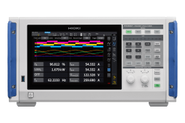
The PW8001 sets a new benchmark for complete power analysis solutions with Hioki being the only manufacturer that offers industry-leading power analyzers and a wide portfolio of high-accuracy current sensors both developed and manufactured by Hioki. This enables to align their performance and results in more accurate and stable measurements from DC to high frequencies and low power factor measurements thanks to functions like the automatic phase shift correction.
The PW8001 sets a new benchmark for complete power analysis solutions with Hioki being the only manufacturer that offers industry-leading power analyzers and a wide portfolio of high-accuracy current sensors both developed and manufactured by Hioki. This enables to align their performance and results in more accurate and stable measurements from DC to high frequencies and low power factor measurements thanks to functions like the automatic phase shift correction.
Upcoming industry challenges are anticipated with the ability to measure even large currents at voltages up to 1500 V, 15 MS/s sampling rate and multi-channel measurement target applications using SiC/GaN semiconductors from automobile electrification, smart grids and reactors to renewable energy supply sources.
Features
*1: When using the 15MS/S Input Unit U7005
*2: When used with a current sensor with automatic phase correction functionality
*3: When using the 2.5MS/S Input Unit U7001
*4: JCSS is standard that is satisfy the requirements of the ISO/IEC 17025 international standard.
Unleashing innovation: Discover version 2.0 with groundbreaking features!
Discover the enhanced Version 2.0 firmware, now with Power Spectrum Analysis (PSA) to accurately analyze high-frequency power loss. Additionally, this latest firmware update brings thoughtful innovations such as improved optical links, IEC harmonics, and flicker management. Explore the refined features of Version 2.0 that blend performance with precision.
Providing the ultimate power analyzer for use by all engineers pursuing power conversion efficiency
Evaluating power conversion efficiency requires the ability to accurately measure power in every band, from DC to high frequencies. The PW8001 delivers exceptional measurement accuracy not only for 50/60 Hz, but also across a broad frequency band, including for DC and at 50 kHz. This allows it to accurately evaluate power conversion efficiency which often involves measuring multiple frequencies.
Accurate capture of power fluctuations caused by high-speed switching
Evaluating power conversion efficiency requires the ability to accurately measure power in every band, from DC to high frequencies. The PW8001 delivers exceptional measurement accuracy not only for 50/60 Hz, but also across a broad frequency band, including for DC and at 50 kHz. This allows it to accurately evaluate power conversion efficiency which often involves measuring multiple frequencies.
Unlocking efficiency in inverter systems: Introducing Power Spectrum Analysis (PSA)
The Power Spectrum Analysis (PSA) function, enhanced by a powerful FFT (Fast Fourier Transform) feature, revolutionizes our approach to analyzing high-frequency power loss. This advanced FFT capability allows for in-depth analysis of voltage, current, and active power, providing detailed insights into power conversion dynamics. This is crucial for enhancing inverter efficiency and minimizing waste in power systems through targeted frequency analysis. The PSA function can provide a clearer picture of electrical issues and helping to pinpoint and reduce power losses more effectively.
Up to 8 power channels optimizing your measurement
Increasingly, hardware like electric vehicle (EV) drive systems that use dual inverters and electric power interchange systems in smart homes are adopting multi-circuit designs in order to utilize energy effectively. A single PW8001 can measure 8 channels of power data, allowing equipment with 8 measurement points for power such as dual motors as well as other equipment with multiple circuits to be evaluated in one stroke.
Seamlessly integrate power analysis: Dual units, single Control for up to 16 channels
By connecting two PW8001 units with an optical cable, measured data can be consolidated in a single PW8001 in real time. The power of a maximum of 16 channels and 8 motors can be simultaneously analyzed and their efficiency and loss can be displayed and recorded with a single unit.
BNC synchronization
Electrical angle measurement function:
For applications requiring up to 32 channels, time-synchronized measurement of 4 PW8001s can be done with BNC cables. (1 is the primary unit, and the 3 others are secondary.) Settings of each unit can be operated on the primary unit. Although the data is saved in each unit, they are time-synchronized for later analysis. Since the measurement-timing is synchronized, this function makes consolidation and analysis easy.
Use cases
Simultaneous measurement of multiple parallel inverters
Issues
Aircraft, ships, and other applications that demand a large amount of drive power sometimes distribute power using multiple inverters that are connected in parallel. When evaluating such systems as a whole, engineers sometimes wish to evaluate power of multiple inverters at the same time. However, if measurements are made separately using multiple power analyzers, the timings of measurement are not aligned making it difficult to combine the data later.
PMSM online parameter measurement
In order to implement fine control of a permanent magnet synchronous motor (PMSM), it’s necessary to assess the motor’s characteristics under actual operating conditions. The PW8001’s electrical angle measurement function can perform voltage and current advance measurement, which is necessary in order to implement vector control of the dq coordinate system. The instrument can calculate Ld and Lq values from electrical angle measurements and ascertain motor parameters under actual operating conditions.
Compensation of torque meter measurement error
Torque meter measurement error has a substantial impact on motor analysis. The PW8001 can perform calculations using a correction table based on user-defined values for nonlinear compensation and friction compensation. The instrument can accurately analyze high-efficiency motors as well.
Safe evaluation of increasingly high-voltage power conditioners
Renewable energy generation systems are being engineered to use increasingly high voltages in order to reduce equipment construction costs and transmission loss. Evaluating generation systems requires instruments that are capable of high-voltage measurement. The PW8001 Input Unit U7001 can safely measure directly input high voltages of up to 1500 V DC (CAT II) and 1000 V DC (CAT III). (The Voltage Cord L1025, which can accommodate 1500 V DC [CAT II] and 1000 V DC [CAT III], is also available.)
Analysis of power loss in reactors
In order to improve power conversion efficiency, it’s necessary to assess power loss in reactors. The lower the reactor’s loss, the lower the power factor, making accurate measurement difficult. The U7005’s outstanding high-frequency characteristics and noise resistance make it an extremely effective tool for analyzing power loss in high-frequency, low-power-factor reactors.
Easy installation even in complicated wiring or narrow/tight spaces
The AC/DC Current Probe CT6830 and CT6831 (optional) have a compact and small-size design, making it easy to install in tight spaces around circuit boards, such as the switching power supplies inside products. Furthermore, they cover a wide operating temperature range from -40°C to 85°C, allowing for accurate measurement of low-level DC currents even in environments where the ambient temperature varies.
| Measurement lines | 1-phase-2-wire, 1-phase-3-wire, 3-phase-3-wire, 3-phase-4-wire |
| No. of PW8001 input units | Max. 8 units (mix and match) |
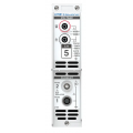
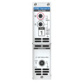
| Type of input unit | U7001 2.5 MS/s INPUT UNIT U7005 15 MS/s INPUT UNIT |
| Measurement frequency band | U7001: DC, 0.1 Hz to 1 MHz U7005: DC, 0.1 Hz to 5 MHz |
| Sampling | U7001: 2.5 MHz, 16-bit U7005: 15 MHz, 18-bit |
| Data update rate | 1 ms, 10 ms, 50 ms, 200 ms |
| Accuracy for power (U7001) | 50/60 Hz: 0.02% of reading + 0.05% of range DC: 0.02% of reading + 0.05% of range 50 kHz : 0.4% of reading + 0.1% of range |
| Accuracy for power (U7005) | 50/60 Hz : 0.01% of reading + 0.02% of range DC : 0.02% + 0.03% of reading of range 50 kHz: 0.15% of reading + 0.05% of range |
| Measurement range | Voltage: 6 V, 15 V, 30 V, 60 V, 150 V, 300 V, 600 V, 1500 V Current: (Probe1) 40 mA to 2 kA, (Probe2) 100 mA to 50 kA (Probe1 : Hioki's high-accuracy current sensor interface supports automatic identification and phase shift correction. Probe 2: BNC I/F only for U7001) |
| Measurement parameters | Voltage (U), current (I), active power (P), apparent power (S), reactive power(Q), power factor (λ), phase angle (φ), voltage frequency (fU), current frequency (fI), efficiency (η), loss (Loss), voltage ripple factor (Urf), current ripple factor (Irf), current integration (Ih), power integration (WP), voltage peak (Upk), current peak (Ipk) Harmonics measurement: (Wideband mode: Maximum analysis order 500th, IEC measurement mode) Waveform recording: recording capacity 5M words x ( [voltage/current] ) x - No. of channels + motor waveforms) Motor analysis (option): voltage, torque, RPM, frequency, slip, motor power FFT analysis (Power spectrum analysis) Flicker measurement |
| IEC measurement mode | When the measurement line has a frequency of 50 Hz or 60 Hz, the instrument can perform harmonic measurements according to IEC61000-4-7 and voltage fluctuation/flicker measurements according to IEC61000-4-15 |
| IEC-compliant harmonic measurement | Compliant with IEC 61000-4-7:2002 Analysis order: Harmonics: 0th to 200th orders, Inter-harmonic: 0.5th to 200.5th orders |
| IEC-compliant flicker measurement | Compliant with IEC 61000-4-15:2010 Ed 2.0 Flickermeter Class F2 Measurement items: Short-term flicker (Pst), Maximum short-term flicker value (PstMax), Long-term flicker value (Plt), Maximum instantaneous flicker value (PinstMax), Minimum instantaneous flicker value (PinstMin), Relative steady-state voltage change (dc), Maximum relative voltage change (dmax), Period while the relative voltage change exceeds the threshold (Tmax) |
| Calculation function | Efficiency and loss calculations, User-defined calculations, Delta conversion, Current sensor automatic phase shift calculation |
| Synchronization measurement | Optical link: Up to two units, 16 channels maximum BNC Synchronization: Up to four units, 32 channels maximum |
| External interface | USB flash drive, LAN, GP-IB, RS-232C, external control, optical link, BNC sync., CAN or CAN FD |
| Power supply | 100 V to 240 V AC, 50/60 Hz, 230 VA |
| Dimensions and mass | Approx. 430 mm (16.93 in) W × 221 mm (8.70 in) H × 361mm (14.21 in) D, Approx. 14kg (493.84 oz) |
Click on a category to view a selection of compatible accessories with the Hioki PW8001-13 High Precision Power Analyzer with Motor Analysis and CAN or CAN FD Output, DC, 0.1 Hz to 5 MHz, 3-phase 4-wire.

| Measurement lines | 1-phase-2-wire, 1-phase-3-wire, 3-phase-3-wire, 3-phase-4-wire |
| No. of PW8001 input units | Max. 8 units (mix and match) |
| Type of input unit | U7001 2.5 MS/s INPUT UNIT U7005 15 MS/s INPUT UNIT |
| Measurement frequency band | U7001: DC, 0.1 Hz to 1 MHz U7005: DC, 0.1 Hz to 5 MHz |
| Sampling | U7001: 2.5 MHz, 16-bit U7005: 15 MHz, 18-bit |
| Data update rate | 1 ms, 10 ms, 50 ms, 200 ms |
| Accuracy for power (U7001) | 50/60 Hz: 0.02% of reading + 0.05% of range DC: 0.02% of reading + 0.05% of range 50 kHz : 0.4% of reading + 0.1% of range |
| Accuracy for power (U7005) | 50/60 Hz : 0.01% of reading + 0.02% of range DC : 0.02% + 0.03% of reading of range 50 kHz: 0.15% of reading + 0.05% of range |
| Measurement range | Voltage: 6 V, 15 V, 30 V, 60 V, 150 V, 300 V, 600 V, 1500 V Current: (Probe1) 40 mA to 2 kA, (Probe2) 100 mA to 50 kA (Probe1 : Hioki's high-accuracy current sensor interface supports automatic identification and phase shift correction. Probe 2: BNC I/F only for U7001) |
| Measurement parameters | Voltage (U), current (I), active power (P), apparent power (S), reactive power(Q), power factor (λ), phase angle (φ), voltage frequency (fU), current frequency (fI), efficiency (η), loss (Loss), voltage ripple factor (Urf), current ripple factor (Irf), current integration (Ih), power integration (WP), voltage peak (Upk), current peak (Ipk) Harmonics measurement: (Wideband mode: Maximum analysis order 500th, IEC measurement mode) Waveform recording: recording capacity 5M words x ( [voltage/current] ) x - No. of channels + motor waveforms) Motor analysis (option): voltage, torque, RPM, frequency, slip, motor power FFT analysis (Power spectrum analysis) Flicker measurement |
| IEC measurement mode | When the measurement line has a frequency of 50 Hz or 60 Hz, the instrument can perform harmonic measurements according to IEC61000-4-7 and voltage fluctuation/flicker measurements according to IEC61000-4-15 |
| IEC-compliant harmonic measurement | Compliant with IEC 61000-4-7:2002 Analysis order: Harmonics: 0th to 200th orders, Inter-harmonic: 0.5th to 200.5th orders |
| IEC-compliant flicker measurement | Compliant with IEC 61000-4-15:2010 Ed 2.0 Flickermeter Class F2 Measurement items: Short-term flicker (Pst), Maximum short-term flicker value (PstMax), Long-term flicker value (Plt), Maximum instantaneous flicker value (PinstMax), Minimum instantaneous flicker value (PinstMin), Relative steady-state voltage change (dc), Maximum relative voltage change (dmax), Period while the relative voltage change exceeds the threshold (Tmax) |
| Calculation function | Efficiency and loss calculations, User-defined calculations, Delta conversion, Current sensor automatic phase shift calculation |
| Synchronization measurement | Optical link: Up to two units, 16 channels maximum BNC Synchronization: Up to four units, 32 channels maximum |
| External interface | USB flash drive, LAN, GP-IB, RS-232C, external control, optical link, BNC sync., CAN or CAN FD |
| Power supply | 100 V to 240 V AC, 50/60 Hz, 230 VA |
| Dimensions and mass | Approx. 430 mm (16.93 in) W × 221 mm (8.70 in) H × 361mm (14.21 in) D, Approx. 14kg (493.84 oz) |
Click on a category to view a selection of compatible accessories with the Hioki PW8001-13 High Precision Power Analyzer with Motor Analysis and CAN or CAN FD Output, DC, 0.1 Hz to 5 MHz, 3-phase 4-wire.