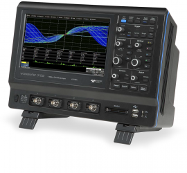
The WaveSurfer 3054z features the MAUI ("Most Advanced User Interface") interface that is designed for smooth touch operation, such that you can confidently control zoom, trigger zones, probes, math functions, and more with taps and gestures. A large 10.1" (25.65 cm) capacitive touch-screen display offers intuitive interaction and 30% more waveform area than many competitors.
The WaveSurfer 3054z features the MAUI ("Most Advanced User Interface") interface that is designed for smooth touch operation, such that you can confidently control zoom, trigger zones, probes, math functions, and more with taps and gestures. A large 10.1" (25.65 cm) capacitive touch-screen display offers intuitive interaction and 30% more waveform area than many competitors.
A 500 MHz analog bandwidth with up to 4 GS/s (single-shot) sample rate, 20 Mpts memory (interleaved), and a standard collection of math, measurement, debug, and documentation tools provides outstanding and unsurpassed anomaly detection and analysis capabilities.
MAUI is the most advanced oscilloscope user interface. It is designed for touch, built for simplicity, and made to solve.
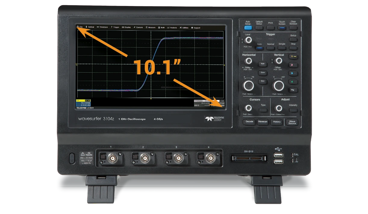
A large capacitive touch screen enables accessible and responsive touch operation. The 10.1" (25.65 cm) display is 30% larger than competitive offerings, providing more waveform viewing area.
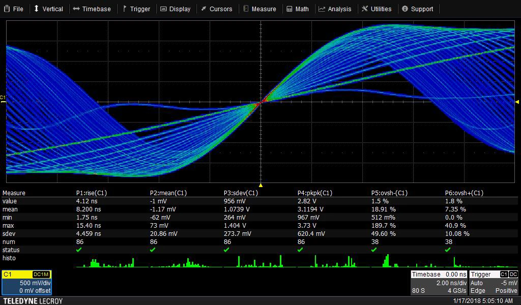
A fast waveform update rate, used in conjunction with history mode, WaveScan, sequence mode, and mask testing facilitates outstanding waveform anomaly detection.
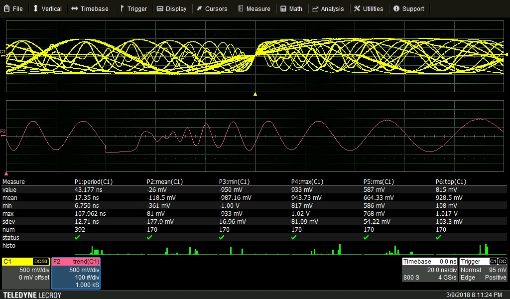
A deep set of integrated debug and analysis tools help identify problems and find solutions quickly. Unsurpassed integration provides critical flexibility when debugging. Solve problems fast with powerful analysis tools.
WS3K-EMB I2C, SPI, UART and RS-232 Trigger and Decode Package
WS3K-PWR Power Analyzer Package
WS3K-FG Function Generator Package
WS3K-Audiobus TD AudioBus Trigger and Decode Package
WS3K-AUTO CAN and LIN Trigger and Decode Package
Flexible CAN and LIN triggering: Break (LIN only), ID, ID + DATA, Remote Frames, Error Frames, Powerful conditional triggering
Supported bit rates: CAN from 10 kb/s to 1 Mb/s, LIN from 1.2 kb/s to 19.2 kb/s
WS3K-CAN FDBUS TD Trigger Decode Package
Supports: Classic CAN, CAN FD, CAN FD Light
WS3K-FLEXRAYBUS TD FlexRay Trigger Decode Package
Features
WaveScan Advanced Search 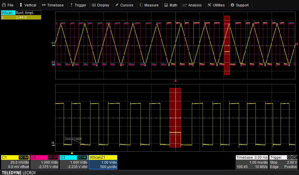
Pass/Fail Mask Testing 
Fast Waveform Update 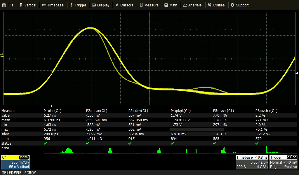
History Mode Waveform Playback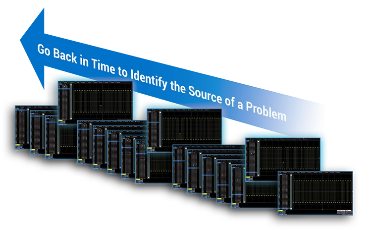
Powerful Triggering 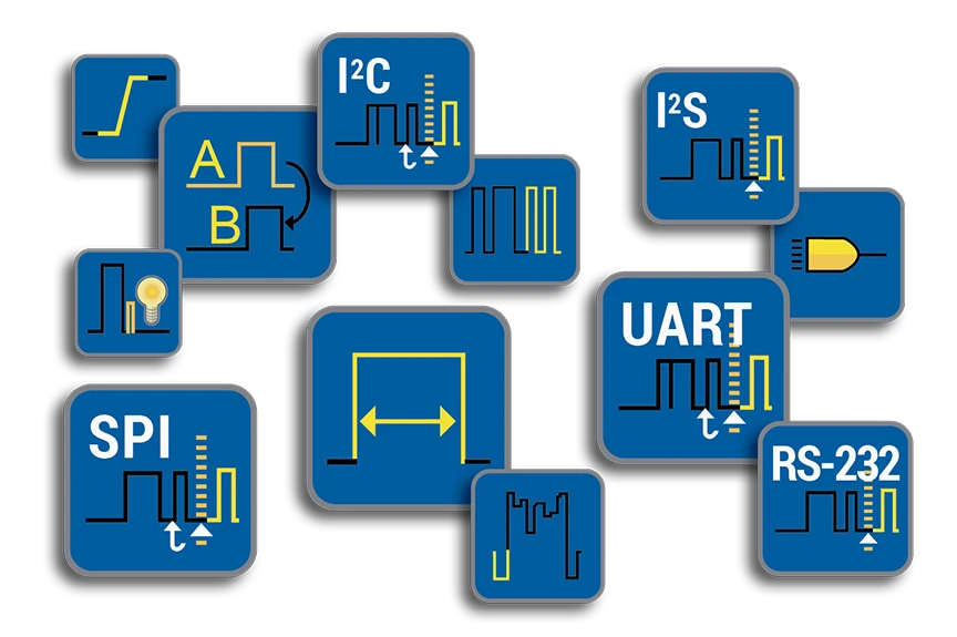
Advanced Waveform Capture with Segmented Memory 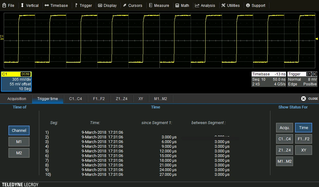
Protocol Analysis with Serial Trigger and Decode 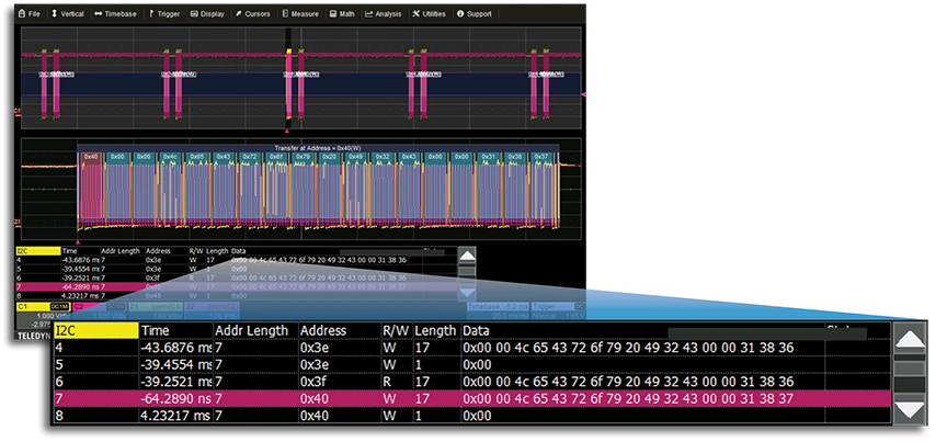
Precise Measurements with Digital Voltmeter 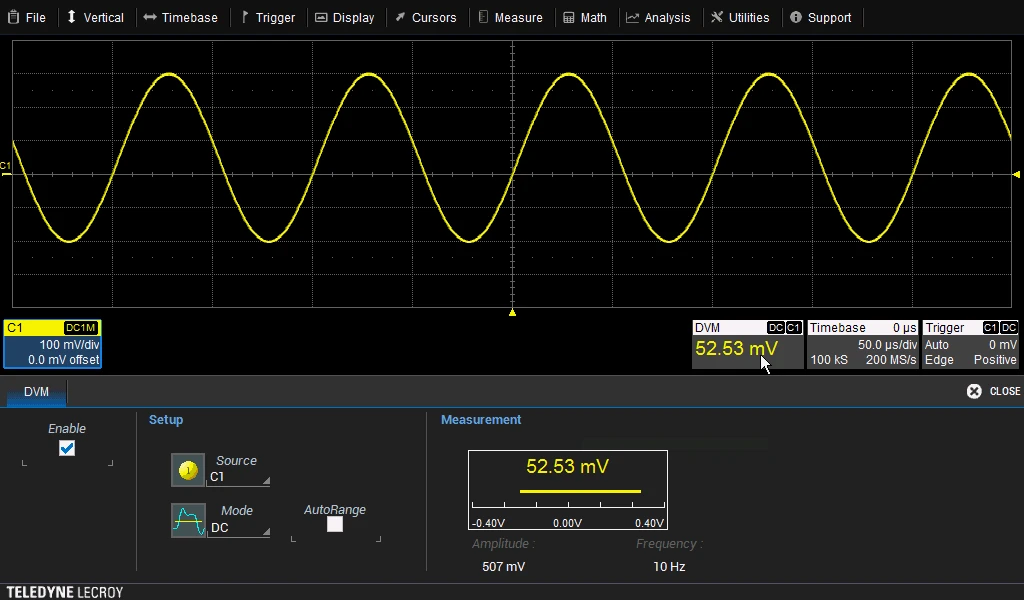
Logic Analysis with 16 Channel Mixed Signal Capability 
Waveform Generation with Built-in Function Generator
Advanced Math Capabilities 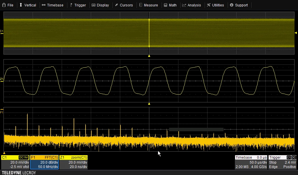
Superior Measurement Tools 
LabNotebook Documentation Tool
Applications
| Vertical Analog Channels | |
| Maximum Analog Bandwidth | 500 MHz |
| Bandwidth | 500 MHz |
| ProBus Input Analog Bandwidth at 50 Ω (-3 dB) | 500 MHz (≥2.35 mV/div) |
| ProBus Input Analog Bandwidth at 1 MΩ (-3 dB) | 500 MHz |
| Rise Time (10 to 90%, 50 Ω) | 800 ns |
| Input Channels | 4 |
| Vertical Resolution | 8 bits: Up to 11 bits with enhanced resolution (ERES) |
| Sensitivity | 1 MΩ: 1 mV/div - 10 V/div, fully variable 50 Ω: 1 mV/div - 1 V/div, fully variable |
| DC Vertical Gain Accuracy | ±(1.5%) Full Scale, offset at 0 V > 5mV; ±(2.5%) < 5mV |
| Channel-Channel Isolation | 40 dB from DC - 100 MHz 33 dB > 100 MHz (For any two ProBus input channels, same v/div settings, typical) |
| Offset Range | 50 Ω ±2 V: 1 mV/div to 19.8 mV/div ±5 V: 20 mV/div to 100 mV/div ±20 V: 102 mV/div to 198 mV/div ±50 V: 200 mV/div to 1 V/div 1 MΩ ±2 V: 1 mV/div to 19.8 mV/div ±5 V: 20 mV/div to 100 mV/div ±20 V: 102 mV/div to 198 mV/div ±50 V: 200 mV/div to 1 V/div ±200 V: 1.02 V/div to 1.98 V/div ±400 V: 2 V/div to 10 V/div |
| Maximum Input Voltage | 1 MΩ: 400 V maximum (DC + Peak AC ≤ 10 KHz) 50 Ω: 5 VRMS |
| Input Coupling | AC, DC, GND |
| Input Impedance | 50 Ω ± 2.0% or 1 MΩ || 16 pF |
| Bandwidth Limiters | 20 MHz |
| Horizontal Analog Channels | |
| Timebases | Internal timebase common to 4 input channels |
| Acquisition Modes | Real-time, Roll, Random Interleaved Sampling (RIS), Sequence |
| Time/Division Range | 500 ps/div to 50 s/div RIS available at ≤ 10 ns/div Roll Mode available at ≥ 100 ms/div and ≤ 5 MS/s |
| Clock Accuracy | 10 ppm > 1 ms interval |
| Channel-Channel Deskew Range | ±9 x time/division setting, 100 ms maximum, each channel |
| Acquisition Analog Channels | |
| Single-shot Sample Rate | 4 GS/s on 2 Ch 2 GS/s on 4 Ch |
| Repetitive Sample Rate | 50 GS/s for repetitive signals (2 ns/div to 10 ns/div) |
| Memory Length | 4 channels: 10M 2 channels: 20M 1 channel: 20M Number of segments: 1000 |
| Enhanced Resolution | 8 bits: Up to 11 bits with enhanced resolution (ERES) |
| Vertical, Horizontal, Acquisition Digital Channels | |
| Maximum Input Frequency | 125 MHz |
| Minimum Detectable Pulse Width | 4 ns |
| Input Channels | 16 Digital channels, with WS3K-MSO option |
| Flying Leads Input Impedance | 100 kΩ || 5 pF |
| Input Dynamic Range | ±20 V |
| Maximum Input Voltage | ±30 V Peak |
| Minimum Input Voltage Swing | 500mVpp |
| Threshold Groupings | Pod 2: D15 - D8 Pod 1: D7 - D0 |
| Threshold Selections | TTL (+1.4 V), 5V CMOS (+2.5 V), ECL (-1.3 V), or User Defined |
| Threshold Accuracy | ±3% of threshold setting + 100 mV |
| User Defined Threshold Range | ±10 V in 20 mV steps |
| Sample Rate | 500 MS/s |
| Record Length | 10 MS - 16 Channels |
| Channel-to-Channel Skew | ±1 digital sample |
| Triggering System | |
| Modes | Normal, Auto, Single, Stop |
| Sources | Ch 1 - Ch 4, EXT, EXT/5, AC Line |
| Coupling | DC, AC, HFRej, LFRej |
| Pre-trigger Delay | 0 to 100% of memory size |
| Post-trigger Delay | 0 to 10,000 Divisions |
| Hold-off | 10 ns up to 20 seconds |
| Internal Trigger Level Range | ±4.1 Divisions |
| External Trigger Level Range | Ext: ±0.61 V Ext/5: ±3.05 V |
| Trigger Sensitivity with Edge Trigger ProBus Inputs | 0.8 division: DC - 10 MHz 1.5 division: 10 MHz to 200 MHz |
| Trigger Sensitivity with Edge Trigger Aux Input | Ext: 200 mV from DC to 10 MHz 300 mV from 10 MHz to 200 MHz Ext/5: 1 V from DC to 10 MHz 1.5 V from 10 MHz to 200 MHz |
| Trigger Types | |
| Edge | Triggers when signal meets slope (positive, negative, or either) and level condition. |
| Width | Triggers on positive or negative glitches with selectable widths. Minimum width 500 ps Maximum width: 20 seconds |
| Window | Triggers when signal exits a window defined by adjustable thresholds |
| Pattern | Logic combination (AND, NAND, OR, NOR) of 5 inputs (4 channels and external trigger input). Each source can be high, low, or don't care. The High and Low level can be selected independently. Triggers at start or end of the pattern. |
| TV-Composite Video | Triggers NTSC or PAL with selectable line and field, HDTV (720p, 1080i, 1080p) with selectable frame rate (50 or 60 Hz) and Line, or CUSTOM with selectable Fields (1 to 8), Lines (up to 2000), Frame Rates (25, 30, 50, or 60 Hz), Interlacing (1:1, 2:1, 4:1, 8:1), or Synch Pulse Slope (Positive or Negative). |
| Runt | Trigger on positive or negative runts defined by two voltage limits and two time limits. Select between 1 ns and 20 ns. |
| Slew Rate | Trigger on edge rates. Select limits for dV, dt, and slope. Select edge limits between 1 ns and 20 ns. |
| Interval | Triggers on intervals selectable between 1 ns and 20 s. |
| Dropout | Triggers if signal drops out for longer than selected time between 1 ns and 20 s. |
| Multi-Stage, Qualified Timeout or State/Edge Qualified | Triggers on any input source only if a defined state or edge occurred on another input source. Delay between sources is selectable by time. |
| Optional Low Speed Serial Protocol Trigger | |
| Supported Protocols | I2C, SPI (SPI, SSPI, SIOP), UART-RS232, CAN1.1, CAN2.0, CAN FD, LIN, FlexRay, AudioBus (I2S, LJ, RJ, TDM) |
| Measurement Tools | |
| Measurement Functionality | Display up to 6 measurement parameters together with statistics, including mean, minimum, maximum, standard deviation, and total number. Each occurrence of each parameter is measured and added to the statistics table. Histicons provide a fast, dynamic view of parameters and waveshape characteristics. Parameter gates define the location for measurement on the source waveform. |
| Horizontal and Jitter Measurement Parameters | Delay (from trigger, 50%), Duty Cycle, Fall Time (90-10, 80-20), Frequency, Period, Delta Period, Phase, Rise Time (10-90, 20-80), Skew, Width+, Width- |
| Vertical Measurement Parameters | Amplitude, Base, Maximum, Mean, Minimum, Peak-to-Peak, RMS, Std Deviation, Top |
| Pulse Measurement Parameters | Area, Base, Fall Time (90-10, 80-20), Overshoot (positive, negative), Rise Time (10-90, 80-20), Top, Width+, Width- |
| Math Tools | |
| Math Functionality | Display up to 2 math functions traces (F1-F2). The easy-to-use graphical interface simplifies setup of up to two operations on each function trace, and function traces can be chained together to perform math-on-math. |
| Basic Math Operators | Average (summed), Average (continuous), Difference (-), Envelope, Exp (base e, base 10), Floor, Invert (negate), Log (base e, base 10), Product (x), Ratio (/), Reciprocal, Rescale (with units), Roof, Sum (+). |
| Filters Math Operators | Enhanced resolution (to 11 bits vertical) |
| Frequency Analysis Math Operators | FFT (power spectrum, magnitude), up to 500 kpts record length. Select from Rectangular, VonHann, Hamming, FlatTop and Blackman Harris windows. |
| Functions Math Operators | Derivative, Integral, Invert (negate), Rescale (with units), Square, Square root, Zoom (identity). |
| Measurement and Math Integration | |
| Measurement and Math Integration | Trend (datalog) of up to 1000 measurement parameters |
| Pass and Fail Testing | |
| Pass and Fail Testing | Mask Test (pre-defined or user-defined mask, waveform All In, All Out, Any In, or Any Out conditions) with following THEN Save (waveforms), Stop, Alarm, (send) Pulse, Hardcopy (send email, save screen image, save to clipboard, send to printer), or (save) LabNotebook. |
| Display System | |
| Size | Color 10.1" (25.65 cm) widescreen flat panel TFT-LCD with high-resolution capacitive touch screen |
| Resolution | 1024 x 600 |
| Number of traces | Display a maximum of 8 traces. Simultaneously display channel, zoom, memory and math traces. |
| Grid Styles | Auto, Single,X-Y, Single+X-Y |
| Persistence Display | |
| Analog and Color-Graded Persistence | Variable saturation levels, stores each trace's persistence data in memory |
| Persistence Types | Select analog or color |
| Trace Selection | Activate persistence on all traces |
| Persistence Aging | Select from 1.00 second to infinity |
| Zoom Expansion Traces | |
| Zoom Expansion Traces | Display up to 4 Zoom and 2 Math/Zoom traces |
| Internal Waveform Memory | |
| Internal Waveform Memory | 2 active waveform memory traces (M1-M2) store 16-bit/point full-length waveforms. Waveforms can be stored to 2 file locations on the scope or the microSD, limited only by the data storage media capacity |
| Setup Storage | |
| Front Panel and Instrument Status | Store to the internal microSD, over the network, or to a USB-connected peripheral device. |
| Automatic Setup | |
| Auto Setup | Automatically sets timebase, trigger, and sensitivity to display a wide range of repetitive signals |
| Find Vertical Scale | Automatically sets the vertical sensitivity and offset for the selected channel to display a waveform with the maximum dynamic range |
| Calibration | |
| Auto Calibration | Ensures specified DC and timing accuracy is maintained for 1 year minimum |
| Processor and CPU | |
| Type | TI AM5728 Sitara Processor |
| Processor Memory | 2 GB |
| Operating System | Microsoft Windows CE |
| Oscilloscope Operating Software | Teledyne LeCroy MAUI™ |
| Real Time Clock | Date and time are displayed with the waveform in hardcopy files. SNTP support to synchronize to precision internal clocks. |
| Connectivity | |
| Ethernet Port | Supports 10/100BaseT Ethernet interface (RJ45 port) |
| USB Host Ports | 4 x USB 2.0 Ports Total 2 x Front USB 2.0 Ports |
| USB Device Port | 1 x port - USBTMC over USB 2.0 |
| Optional GPIB Port | Supports IEEE - 488.2 (External) |
| External Monitor Port | Standard DB-15 connector Support resolution of 1024x600 |
| Remote Control | Via Windows Automation, or via LeCroy Remote Command Set |
| Network Communication Standard | VXI-11 or VICP, LXI Compatible |
| Auxiliary Input | |
| Signal Types | Select External Trigger on the rear panel |
| Coupling | 50 Ω: DC 1 MΩ: AC, DC, GND |
| Maximum Input Voltage | 50 Ω: 5 Vrms 1 MΩ: 250 Vmax (DC + Peak AC ≤ 10 kHz) |
| Auxiliary Output | |
| Signal Types | Always trigger out |
| Output Signal | 3.3 V into 1 MΩ pulse > 1.3 ms |
| Control Signals | Trigger out |
| Connector Type | BNC, located on back |
| Probes | |
| Probing System | ProBus automatically detects and supports a variety of compatible probes |
| Probes | 4 x ÷10 passive probes |
| Scale Factors | Automatically or manually selected, depending on the probe used |
| Calibration Output | The default is a 1 kHz square wave with a 3.3 Vp-p (typical) output to the probe hook. Settable from 500 Hz to 1 MHz square wave. |
| Power Requirements | |
| Voltage | 100 to 240 VAC, 50 Hz to 60 Hz ±5% 100 to 120 VAC, 400 Hz ±5% |
| Maximum Power Consumption | 330 VA |
| Environmental | |
| Temperature | Operating: 32 to 122°F (0 to 50°C) Storage: -22 to 158°F (-30 to 70°C) |
| Humidity | Operating:
Storage:
|
| Altitude | Operating: 10,000' (3048 m) maximum at <= 77°F (25°C) Storage: 40,000' (12,192 m) |
| Certifications | |
| CE Certification | CE Compliant, UL and cUL listed; conforms to |
| UL and cUL Listing | UL 61010-1 (3rd Edition), UL 61010-2-030 (1st Edition) CAN/CSA C22.2 No. 61010-1-12 |
| Warranty and Service | |
| Warranty and Service | 3-year warranty. Calibration is recommended annually. Optional service programs include extended warranty, upgrades, and calibration services. |
| Size and Weight | |
| Dimensions | 10.63 x 14.96 x 4.92" (270 x 380 x 125 mm) |
| Weight | 10.6 lbs (4.81 kg) |